Ace Tips About What Is The Relationship Between Voltage And Resistance In A Series Circuit

Unlocking the Secrets of Voltage and Resistance in Series Circuits
1. Understanding the Players
Ever wondered how electricity flows through those intricate circuits powering your gadgets? It's like a tiny river, and two key players are voltage and resistance. Voltage is like the pressure pushing the water, and resistance is like the rocks and pebbles in the riverbed slowing it down. In a series circuit, these two have a very special relationship, almost like a well-choreographed dance.
Think of voltage as the "oomph" behind the electric current. It's what motivates those electrons to get moving and do some work. Resistance, on the other hand, is the opposition to that flow. It's what makes the electrons work harder to get through the circuit. This opposition generates heat, which is why your light bulb gets warm!
Now, what happens when these two meet in a series circuit? A series circuit, just so we're clear, is where components are connected one after the other, like train carriages. There's only one path for the current to travel. Imagine a line of resistors stubbornly standing in the way of our energetic voltage.
In essence, understanding the interplay of voltage and resistance is core to grasping how these circuits function. Voltage wants to push, resistance wants to hold back. Finding that perfect balance is where the magic of electronics truly happens!
2. The Golden Rule
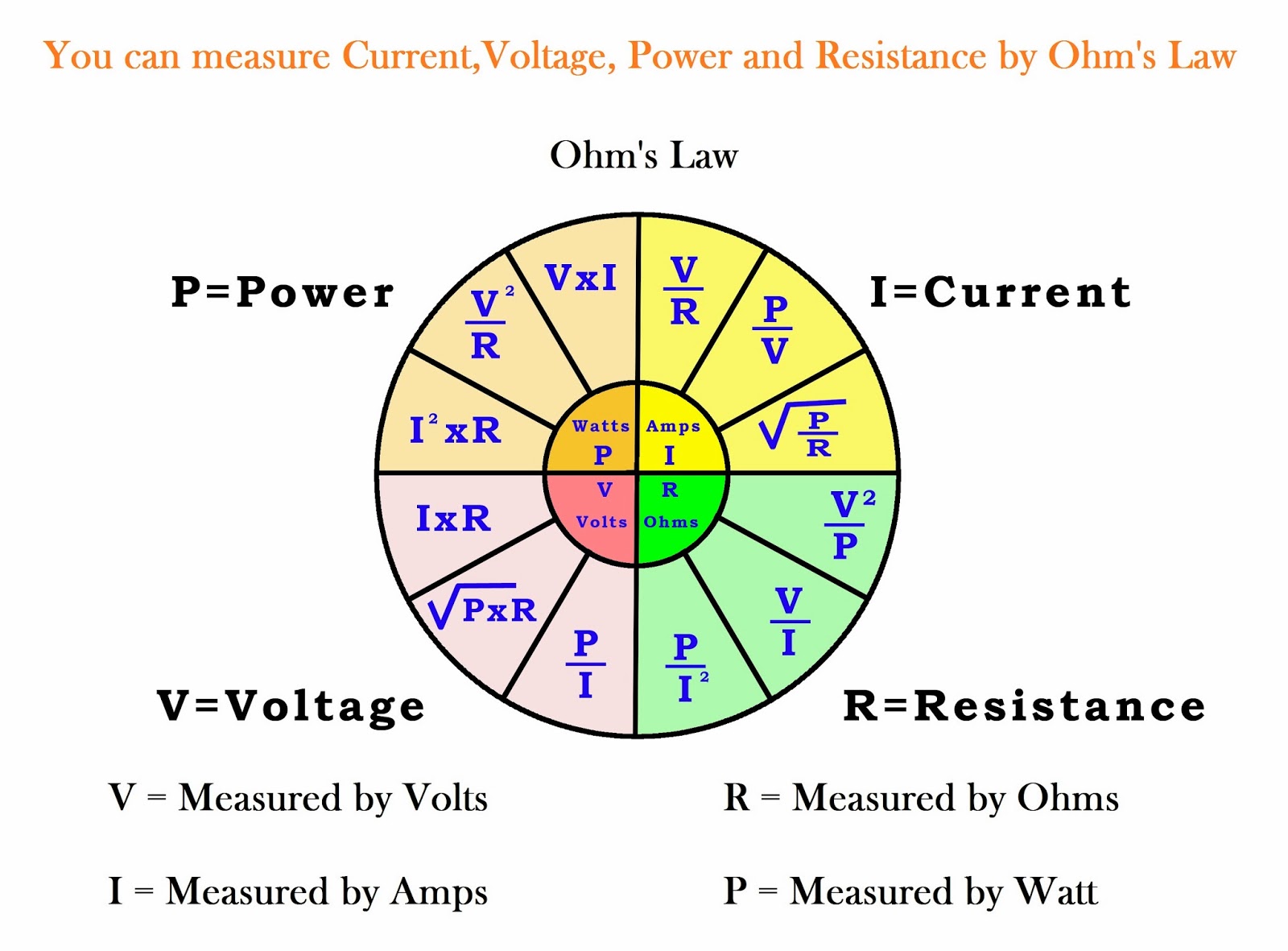
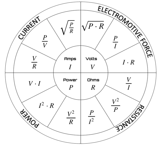
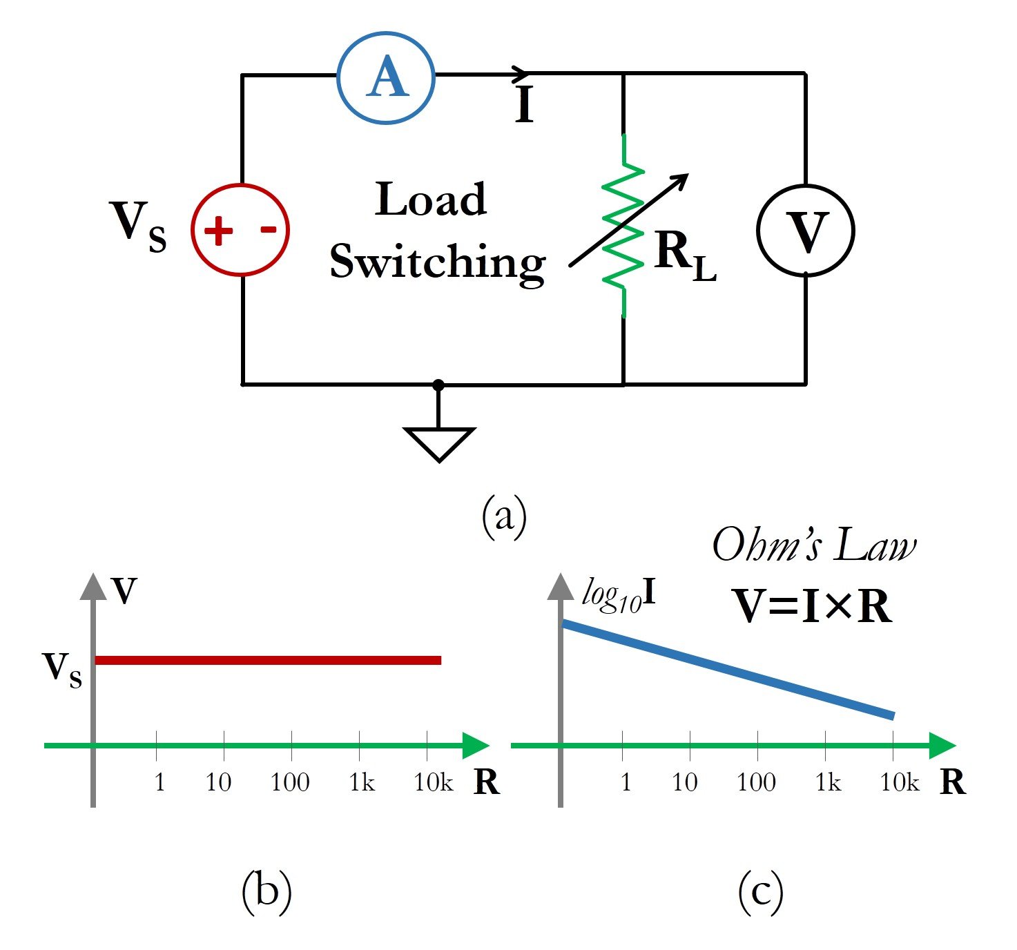
Ohm's Law is the maestro of this electrical orchestra, dictating the exact relationship between voltage, resistance, and current. It's expressed with a simple equation: V = IR (Voltage = Current x Resistance). This is your new best friend in the world of circuits. Dont worry, it's not as scary as it looks!
So, how does Ohm's Law play out in a series circuit? Well, since the current has only one path to follow, it's the same throughout the entire circuit. But here's the kicker: the voltage gets divided up amongst all the resistors. Each resistor "eats" a portion of the total voltage, depending on its individual resistance.
Imagine a race where everyone has to go through several roadblocks before they finish the race. Now, these roadblocks are of different sizes and require different efforts to overcome. Those roadblocks are resistance. The voltage has to push through them all.
If you increase the total resistance in the series circuit, the total current will decrease (assuming the voltage stays constant). Conversely, if you decrease the total resistance, the total current will increase. The voltage is simply distributed, but how does it do it? It is proportionally! The biggest resistors will take the biggest bites of voltage.
3. Voltage Division
The concept of "voltage division" is key in a series circuit. Since the current is constant, each resistor gets a slice of the voltage pie based on its resistance value. The larger the resistance, the larger the voltage drop across it. Think of it like splitting a pizza, the person who does most of the work gets the biggest slice.
Let's say you have a 12V power source and two resistors in series: one is 10 ohms and the other is 20 ohms. The 20-ohm resistor will "consume" twice as much voltage as the 10-ohm resistor. This allows you to control and manipulate the voltage at different points in your circuit.
Voltage division can be calculated using a simple formula. The voltage drop across a resistor (Vx) in a series circuit is equal to the total voltage (Vt) multiplied by the ratio of that resistor's resistance (Rx) to the total resistance (Rt): Vx = Vt (Rx / Rt). Armed with this formula, you can predict exactly how the voltage will be distributed.
It is used in voltage regulators and volume controls. It is essential to the design of complex electronic systems! We must always remember, a high resistance will equate to a high amount of voltage drop, and a low resistance will result to low voltage drop.
4. Resistance Summation: Adding Up the Obstacles
When you have multiple resistors lined up in a series circuit, calculating the total resistance is a breeze. You simply add them all together! Rt (Total Resistance) = R1 + R2 + R3 + and so on. It's like adding up the lengths of all the sections of a hiking trail to find the total distance.
This total resistance is what the voltage source "sees" when it's trying to push the current through the circuit. A higher total resistance means the current flow will be lower, and a lower total resistance means the current flow will be higher (again, assuming the voltage remains constant).
Let's say you're building a simple LED circuit. You need to add a resistor in series with the LED to limit the current and prevent it from burning out. If you choose the wrong resistor value, your LED might be too dim or, even worse, go poof*! Getting that total resistance right is essential.
Resistance Summation is the foundation on which circuit designers determine current and voltage levels throughout the entire circuit! If you master calculating total resistance, youre well on your way to mastering basic circuit analysis.
5. Practical Applications
Series circuits might seem simple, but they're used everywhere! From the Christmas lights strung across your house to the simple circuits inside your remote control, series connections are a fundamental building block of electronics.
Consider the case of Christmas lights. One single break in the circuit, and BAM! It all goes dark. The upside is, because the components are so simple, the whole string is relatively cheap to produce.
In more complex applications, series resistors are used for voltage division, setting bias voltages in transistors, and providing current limiting for delicate components like LEDs. Think about those multi-colored LED strips that everyone loves to put up; they all work by voltage division and constant current.
Understanding how voltage and resistance interact in series circuits is not just an academic exercise; it's a crucial skill for anyone working with electronics. Whether you're troubleshooting a broken appliance or designing a new gadget, knowing these principles will save you time, frustration, and maybe even a few burnt-out components!

Circuit Analysis Part 1 Electric Charge, Voltage, Current, And
Frequently Asked Questions (FAQs)
6. Q
A: If one resistor fails (opens) in a series circuit, it breaks the entire circuit. The current flow stops completely, and everything downstream stops working. It's like a broken link in a chain.
7. Q
A: The total voltage in a series circuit is the sum of the voltage drops across each resistor. You can use Ohm's Law (V = IR) to calculate the voltage drop across each resistor and then add them up.
8. Q
A: Neither type is inherently "better." They both have their own strengths and weaknesses. Series circuits are simple and useful for current limiting, but a failure in one component can take down the entire circuit. Parallel circuits offer multiple paths for current flow, so a failure in one branch doesn't affect the others, but they can draw more current overall.


Resistors Calculating The Voltage Dropped In A Series/parallel

Ohm's Law Exploring The Relationship Between Current, Voltage, And
